Lightbar power
Moderator: BCDelica
-
Nordo

- Posts: 80
- Joined: Wed Sep 22, 2010 11:50 am
- Member's Photo Album: http://www.delica.ca/Photos/
- Vehicle: 93 Exceed
- Location: Lethbridge AB
Lightbar power
Im about to start building my light bar. Welding up some aluminum and drillin' some holes and makin' a gutter mount style bar to connect some lights on. I've seen lots of great ideas from other deli's out there, but I haven't seen where people are running the wires. If I am going to start drilling holes in the rig, Id really like some suggestions on where to start. If you got links or pictures on what you or maybe others have done, I sure would appreciate it a ton!!
I only break stuff so i can put bigger stuff on.....

Re: Lightbar power
The cleanest way to enter the van from the roof is though the rear hatch. For a Light Bar this would only work if you have a roof carrier as well. If so, there is lots of space for several wires. You can enter the van through the tail light for small wires ( typical for lighting) or if necessary you can drill and seal in this area with little problem. I ran a 50A feed from the front of the van to a fuse box I located near the rear washer fluid bottle. If you take off the side panel there is lots of space for relays which will give you the opportunity to have multiple switching either with the key on or off. Princess Auto has the plug in relays on sale now for $5.
In addition to the power wire to the rear you will either need control wires or a small radio system you can also get @ Princess Auto. Instead of switches like I have you would have a key fob. I have 2 fobs with my system which control my boat loader as well as aux lights in parallel with the switches. This makes it nice if you fish late you can turn on a light before you get to shore!
Wiring can either be temporary as I use on the boat loader or permanent for the driving lights I have @ the front that stay on the loader when I take it off in the winter.
Before you start it's always a good idea to think of other things you may want power for such as aux batteries, inverter or other 12 V equipment. Good luck with your lights and if you have any other questions just ask.
Larry
- Attachments
-
- Small wiring through tail light
- LC_003.jpg (112.16 KiB) Viewed 5321 times
-
- 6 fuse panel near bottle
- LC_004.jpg (70.84 KiB) Viewed 5321 times
-
- Typical relays
- LC_009.jpg (126.39 KiB) Viewed 5321 times
-
- Auxiliary lights
- LC_008.jpg (94.75 KiB) Viewed 5321 times
-
- Miscellaneous Swithes
- LC_006.jpg (129.06 KiB) Viewed 5321 times
-
- Temporary wiring - stick on pads
- LC_010.jpg (89.16 KiB) Viewed 5321 times
-
- Permanent wiring - rubber clamp
- LC_011.jpg (50.17 KiB) Viewed 5321 times
Re: Lightbar power
My first 2 pictures got cut off so here they are.
- Attachments
-
- Wiring from the roof
- LC_002.jpg (97.61 KiB) Viewed 5320 times
-
- Wireway
- LC_001.jpg (73.14 KiB) Viewed 5320 times
-
macro

- Posts: 646
- Joined: Fri Sep 23, 2011 4:37 pm
- Member's Photo Album: http://www.delica.ca/Photos/
- Vehicle: L400 "The Invader"
- Location: Toronto, ON
Re: Lightbar power
So, your on/off switch isn't on the power wiring, it's connected through a relay? If that's a dumb question, I apologize, I'm a plumber, electricity freaks me out.
-Mat
http://www.expeditionportal.com/forum/t ... ost1813771
@delicacanada on Instagram
http://instagram.com/delicacanada/
http://www.expeditionportal.com/forum/t ... ost1813771
@delicacanada on Instagram
http://instagram.com/delicacanada/
Re: Lightbar power
Yep that's right. I have 2 separate fused control power which provides power to operate the relays through the individual switches. This allows some relays to operate all the time and others must have the key on to operate. You can even have 2 or more switches operate one relay. The control wiring can be small. I used an old 25 pr. telephone cable for mine so I could have lots of switches or multiple options if I wished.
-
macro
- Posts: 646
- Joined: Fri Sep 23, 2011 4:37 pm
- Member's Photo Album: http://www.delica.ca/Photos/
- Vehicle: L400 "The Invader"
- Location: Toronto, ON
Re: Lightbar power
That makes sense, then you can route the power the most direct route and have the small control wiring wherever you want. Where do you buy your fuse boards and whatnot? PA or a secret online retailer perhaps? If you mount any relays outside of the cabin do you use a waterproof one? Or do you try and keep them all together in the cabin?
-Mat
http://www.expeditionportal.com/forum/t ... ost1813771
@delicacanada on Instagram
http://instagram.com/delicacanada/
http://www.expeditionportal.com/forum/t ... ost1813771
@delicacanada on Instagram
http://instagram.com/delicacanada/
-
Super Exceeded
- Posts: 620
- Joined: Mon Aug 16, 2010 11:09 am
- Member's Photo Album: http://www.delica.ca/Photos/
- Vehicle: 1993 L300S
- Location: South Surrey
Re: Lightbar power
My roof mounted lights run with a relay from the high beam leads. This means I can only put them on if the High beams are on. This is handy when driving at night as flicking off the high beams also turns off the over head lights with on coming traffic. I actually drilled a hole just below the drip edge just behind the pax seat to get the wires out.
Re: Lightbar power
I mounted all my relays in the wall cavity so they are all dry. You just need to make a small mounting plate. There is lots of room and with the L300 access is easy through the tail light. If you are only buying 1 or 2 of things PA is best. If you order lots of stuff I have 2 suppliers I use in the states and they will ship USPS so duty etc. is zero. It takes a few weeks but that gives you lots of time to plan!
Larry
Larry
-
macro
- Posts: 646
- Joined: Fri Sep 23, 2011 4:37 pm
- Member's Photo Album: http://www.delica.ca/Photos/
- Vehicle: L400 "The Invader"
- Location: Toronto, ON
Re: Lightbar power
Nice! Thanks! I have plans in my head for a project for next year. Aux battery, lights, inverter, etc etc. I'm just trying to slowly wrap my head around what I want to do and how to do it all properly.
-Mat
http://www.expeditionportal.com/forum/t ... ost1813771
@delicacanada on Instagram
http://instagram.com/delicacanada/
http://www.expeditionportal.com/forum/t ... ost1813771
@delicacanada on Instagram
http://instagram.com/delicacanada/
-
Nordo
- Posts: 80
- Joined: Wed Sep 22, 2010 11:50 am
- Member's Photo Album: http://www.delica.ca/Photos/
- Vehicle: 93 Exceed
- Location: Lethbridge AB
Re: Lightbar power
Thanks for the post irp374!! Nice pics. I don't know yet what I will be doing for a roof carier, but now you have me thinking. There will be one, but I haven't made any designs yet, so I am going to hold off on drilling any holes, but the wiring of the lights you installed is very interesting! I am still trying to figure out what a relay actually does. But thanks for the posts..... food for thought!!
I only break stuff so i can put bigger stuff on.....
-
Erebus

- Posts: 1369
- Joined: Mon May 28, 2007 7:55 pm
- Member's Photo Album: http://www.delica.ca/Photos/
- Vehicle: 1992 Super Exceed
- Location: Edmonton, Alberta
- Location: Edmonton (was Calgary until 2017), Alberta, Canada
- Contact:
Re: Lightbar power
I'm rather late to this thread. Sorry, I haven't been on the forum that much lately. But since I have quite a bit of stuff on the roof, and I've done it without drilling any holes, I figured I'd finally get around to posting this stuff.
I have the following stuff on the roof rack, so I've got lots of wires going up there:
- Turn signal both on the front of the rack and the back
- Brake lights on the back of the rack
- ditch lights on all 4 corners, each separately controlled
- driving/flood lights on the front (LEDs)
- 3 ham antennas, with 3 runs of coax wire
How do I get them up there?
First the ham antennas: 2 of them use very thin RG-174 wires, the 3rd uses RG-58 (same as CB antenna wire).
One RG-174 goes out the cabin through the window behind the driver. It goes up the channel between the window and the frame at the front of the window. The RG-58 antenna wire (same as CB antenna wire) goes out through the driver's side rear window, just like the RG-174. The RG-58 is very visible in the photo, the RG-174 not so much.
The other RG-174 goes out the sliding door and up under the weatherstripping to the roof rack and wraps around the roof rack mounting foot. It follows the same route as the 3 blue 16 gauge wires for the front ditch lights and 4x4 floods.
The two black 16 gauge wires for the rear ditch lights go out the passenger side back window, then snake up around the awning and up the roof rack mounting foot. Once on the rack, the wires go in loom to the rear to the lights.
The turn signals and brake lights are all LED, so draw very little current. So I used Cat4 cable I had laying around. There are 2 wires, one for each side. They are simply spliced into the existing brake and turn signal wires, no relays or fuses involved. They go up the driver's side "under" the tailgate, exiting from behind the tail light by the rear washer filler cap, then up by the tailgate struts, then along the drip rails to the roof rack mounting feet and up.
There is a lot of wiring loom on the roof rack!
Continued in Part 2.
I have the following stuff on the roof rack, so I've got lots of wires going up there:
- Turn signal both on the front of the rack and the back
- Brake lights on the back of the rack
- ditch lights on all 4 corners, each separately controlled
- driving/flood lights on the front (LEDs)
- 3 ham antennas, with 3 runs of coax wire
How do I get them up there?
First the ham antennas: 2 of them use very thin RG-174 wires, the 3rd uses RG-58 (same as CB antenna wire).
One RG-174 goes out the cabin through the window behind the driver. It goes up the channel between the window and the frame at the front of the window. The RG-58 antenna wire (same as CB antenna wire) goes out through the driver's side rear window, just like the RG-174. The RG-58 is very visible in the photo, the RG-174 not so much.
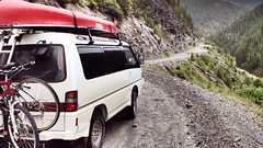
- The roof. You can see the thicker RG-58 coax coming out the back side window, which goes to the very short antenna on the centre of the roof. The thin RG-174 coax coming out the front side window goes to the vertical antenna directly above the rack mounting foot. The rear brake and turn signals are pretty obvious, as are the rear ditch lights (pointed 45 degrees to the rear). One of the front ditch lights is visible.
- A. Roof, cropped 20194.jpg (44.76 KiB) Viewed 4942 times
- The blue wires for the lights, the black RG-174 antenna wires come out of the front of the sliding door and go up around the awning and up the roof rack's mounting foot. The small light is 1/2 of the left front ditch light. The other 1/2 is more obvious, and is labelled, in the photo of the front of the rack. The 4x4 floods are LED, but the wiring is 16 gauge, enough to switch to halogen or higher powered LED as needed without re-wiring. Oh, and there is another RG-58 antenna coax in this bundle that goes to the stud mount above the awning. It is used for either a CB or ham co-linear antenna.
- B. P1020487.JPG (167.67 KiB) Viewed 4942 times
- Just ignore the big light bar, antennas and pylons.
- C. Front roof 20039.jpg (52.25 KiB) Viewed 4942 times
- The passenger sliding door is on the left, the back window is on the right.
- D. P1020489.JPG (69.44 KiB) Viewed 4942 times
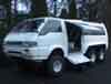
- Rear tailgate, top of tail light and w/w fluid fill cap.
- E. P1020490.JPG (133.21 KiB) Viewed 4942 times
Continued in Part 2.
 "I could be just around the corner from heaven, or a mile from hell." -- Jackson Browne, "The road and the sky".
-
Erebus
- Posts: 1369
- Joined: Mon May 28, 2007 7:55 pm
- Member's Photo Album: http://www.delica.ca/Photos/
- Vehicle: 1992 Super Exceed
- Location: Edmonton, Alberta
- Location: Edmonton (was Calgary until 2017), Alberta, Canada
- Contact:
Re: Lightbar power
Part 2 of my rack.
All the lights are relay controlled from the front console.
The relays for the lights are hidden under the side step of the sliding door -- the plastic step has angled corners, but the metal behind has square corners, leaving lots of space for the relays. After I took this photo, a similar mount was added in the front corner of the step for the front ditch lights and 4x4 flood.
The power for all the relays comes via two 10-gauge wires from the battery -- with a 40-amp circuit breaker right at the battery. One wire goes to the front set of relays, the other to the back set. The closeup shot of the relays shows it before the power wires in and out, as well as the control wires were added. The control wires are the 22-gauge wires shown in the photo going from the numbered terminal block to each relay. The cat-4 cable from the switch/control box attaches to the terminal strip. The power in goes to the back of the fuse block, then is distributed to each relay through the fuse for that circuit. The power wire from the relay to the actual lights is also not shown.
The lighting (except the brake and turn signals) is all relay-operated, controlled by low-current circuits through a switch box that sits on the coolbox. One run of cat-4 brings in power from the circuits that will be used to trigger the stuff, the second run takes the output of the switches to the relays to actually turn on the lights.
I'll leave out the details of how I get the "sense" power to the switch box. But from the switch box there is a single cat-4 run to the side step and the two sets of relays there that power it all.
Most of the switches are double-pole-double-throw switches, with the light being in "Auto" with the switch in the forward position and turned on with the switch in the rear position (if the key is in ACC position), and OFF in the centre. The Auto position is controlled by either high beams (for the front lights) or putting the transmission in reverse (rear ditch lights and backup lights). There are also backup lights mounted under the trailer hitch/bumper that I haven't mentioned, but the switch and relay are in the photos. The rear fog light wiring exists to the rear bumper, but has not yet been installed, and it is only "ON" if parking lights are on. The backup beeper switch is simply on/off; in the on position it is triggered by the transmission in reverse. It has the off position so that when I'm leaving or arriving home very early or very late, I don't wake up the neighbours.
And now I'm sure quite a few of you are asking, "do you really use all that?" The answer is YES. We just got back from a 7000 km trip from Calgary down to the Grand Canyon and back with a few detours. At one time or another, I used every one of the lights. And when I'm doing event communications, I often use them, and additional antennas are added, with the coax antenna leads going through the windows as a temporary install (you can see some in the photo of the front of the Deli and in my current sig file photo).
(Heck, I haven't even mentioned the wiring for my daytime running lights, nor the driving lights, nor the other wiring that provides power for various things. That's for another post some other time! )
)
All the lights are relay controlled from the front console.
The relays for the lights are hidden under the side step of the sliding door -- the plastic step has angled corners, but the metal behind has square corners, leaving lots of space for the relays. After I took this photo, a similar mount was added in the front corner of the step for the front ditch lights and 4x4 flood.
- Step with plastic cover removed. Relays for the rear lights in the corner.
- F. Step relays 10169.jpg (84.57 KiB) Viewed 4940 times
- Closeup of relays.
- G. Relay closeup 10168.jpg (66.78 KiB) Viewed 4940 times
The lighting (except the brake and turn signals) is all relay-operated, controlled by low-current circuits through a switch box that sits on the coolbox. One run of cat-4 brings in power from the circuits that will be used to trigger the stuff, the second run takes the output of the switches to the relays to actually turn on the lights.
I'll leave out the details of how I get the "sense" power to the switch box. But from the switch box there is a single cat-4 run to the side step and the two sets of relays there that power it all.
Most of the switches are double-pole-double-throw switches, with the light being in "Auto" with the switch in the forward position and turned on with the switch in the rear position (if the key is in ACC position), and OFF in the centre. The Auto position is controlled by either high beams (for the front lights) or putting the transmission in reverse (rear ditch lights and backup lights). There are also backup lights mounted under the trailer hitch/bumper that I haven't mentioned, but the switch and relay are in the photos. The rear fog light wiring exists to the rear bumper, but has not yet been installed, and it is only "ON" if parking lights are on. The backup beeper switch is simply on/off; in the on position it is triggered by the transmission in reverse. It has the off position so that when I'm leaving or arriving home very early or very late, I don't wake up the neighbours.
- Switchbox location overview.
- H. P1020486.JPG (151.86 KiB) Viewed 4940 times
- Switchbox closeup.
- I. P1020485.JPG (160.02 KiB) Viewed 4940 times
(Heck, I haven't even mentioned the wiring for my daytime running lights, nor the driving lights, nor the other wiring that provides power for various things. That's for another post some other time!
"I could be just around the corner from heaven, or a mile from hell." -- Jackson Browne, "The road and the sky".