Page 2 of 3
Posted: Tue Feb 20, 2007 8:48 am
by Mystery Machine
Thanks for the info about the glow plug system.... :D
If it is the Super Quick Glow system that you want to check, let me know because I can lay my hands on pretty much all the diagnostic data for checking the function of the whole system! (I can get the data for all the systems, but narrowing it down to the type of system that is faulty is helpful before I go posting TOOO much info! :lol: )
I can get detailed info on the following parts of the system:

Pin allocation and full diagnostic checklist for the complete
Glow Control Unit
Information and diagrams on checking the
Water Temp Sensor
Inspection diagrams and checks of the
Starter Relay
Diagrams & info on checking
'Dropping' Resistor (Super Quick system only)
Full diagnostic checks of both
Glow Plug Relays
Let me know where to start and I'll get on with posting the info up here (it'll take some time though, so please be patient!

)
Regards,
Bruce.
Posted: Tue Feb 20, 2007 10:41 am
by niekt
Wouldn't it be a good idea to post all this info in a seperate "downloads" section so we can find the info's without having to search in all last year's postings ?

Glow Plug
Posted: Tue Feb 20, 2007 6:10 pm
by Delicagibsons
Wow! Wiring diagrams, photos, drawings Thanks for all the info! I'll try to get into the relays tonight to determine what kind of system I have and then with all the help here I'm sure we can figure this out. Steve
glow plugs
Posted: Tue Feb 20, 2007 10:58 pm
by Delicagibsons
OK...I am dealing with the super quick glow system and I've done a bit of trouble shooting. Fist of all, correct me if I'm wrong.
2 relays, one feeds full voltage to the glow plugs for a short period of time (5 seconds or so) The secone relay feeds alower voltage for a longer period of time to keep them warm while the engine warms up Right? OK, I've got a green/black wire feeding the high voltage relay and a green wire feeding the lower voltage relay. It's the low voltage relay that's clicking. When I disconnect the wire, no click. If I put a meter on the green wire to ground I can see that it's switching on and off, on and off, hense the click. It was easier with a test light.
So, my first question is....is the low voltage relay triggered by a timer only or is there some kind of "engine warmed up" sensor as well? ( this would indicate either a faulty glow control circuit or a faulty sensor) If there's some sort of sensor, where would I find it, and what colour wire am I looking for. I assume it runs from the sensor (if there is one) to the glow control box
Second. What if I just disconnect the low voltage relay (the green wire) and just leave it off? I still get the high voltage start glow but not the "keep it warm" glow. It's not that cold out right now. I'll see how it starts tomorrow
Any help on this is awesome! thanks Steve
Posted: Wed Feb 21, 2007 3:28 am
by Mystery Machine
niekt wrote:Wouldn't it be a good idea to post all this info in a seperate "downloads" section so we can find the info's without having to search in all last year's postings ?
Good idea Niek, I'll see what Mark says.....after all, it's not up to me to choose? :lol:
Steve - I am working on the diagrams and info right now - but I think it is gonna take me a while to get it all sorted! (I'm not too quick at typing!
)
I'll report back once I've got it all finished!

(this reminds me of the days when I did all the research and collation for my thesis! :lol: )
Regards,
Bruce.
Posted: Wed Feb 21, 2007 5:42 am
by Mystery Machine
Right,
After
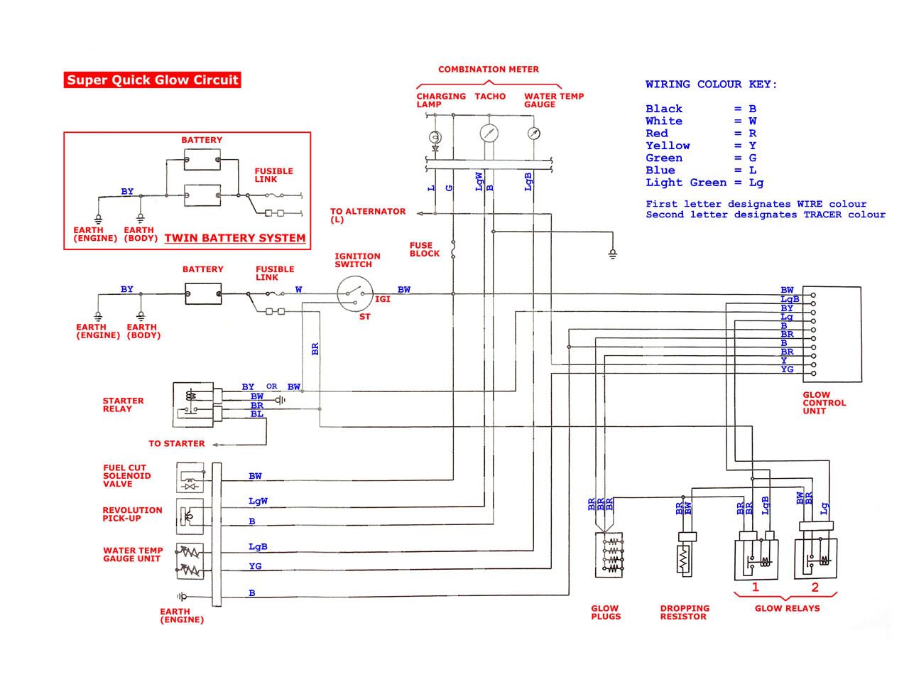
MUCH work trying to turn it into something you can actually make sense of from a really bad paper copy, I have finally cracked it!!
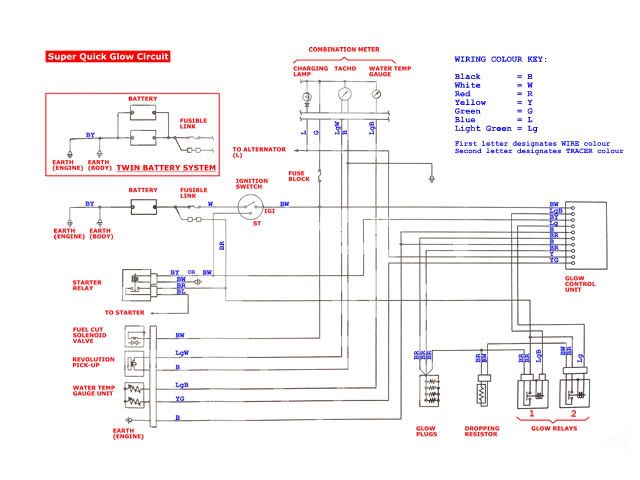
It's a bit too small to make out in this size, so
HERE is a better sized image of the
complete wiring diagram for the Super Quick Glow System :D :D
I have not put it up as a direct image link because might be a bit large for some monitors!
If you want a much bigger 2,500 x 2000 pixel version (just in case you want to print out in hi-res??) then
CLICK HERE 8) 8)
Hope that is a start??
I'll get to work on the other parts of the system when I get time! Maybe not today I'm afraid
(The next bits will be all the diagnostic checklists for every wire/pin in the main glow-plug circuit....

) I've digitized, edited and labelled all the drawings, it's just the 'fun' part of typing in all the data now!

Watch this space...... :lol:
Regards for now,
Bruce.
P.S. PLEASE NOTE - the 'IGI' shown in the diagram by the ignition switch should actually be 'IG1'!! This is more obvious when comparing the diagram to the diagnostic checklist that I will post up later....
It was a VERY poor copy of the wiring diagram and it was only when producing the dignostic list did I notice that it is a '1', not an 'I'!
Sorry about that!

Posted: Wed Feb 21, 2007 7:12 am
by Mystery Machine
.....and here is the diagnostic info for the Glow Control Unit:
The unit can be found inside the 'B' Pillar to the right of the drivers shoulder (just above the access hatch for the air filter etc...)
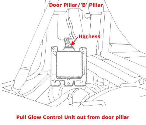
The diagram below shows the pin configuration of the harness plug for the control unit.
I have written up all the diagnostic information associated with this unit (took me a few minutes I can tell you! :lol: ) but it doesn't translate too well without keeping it in a table, so have uploaded it as a Word document with all the table intact as well as screen-grabbing the document to make the image below:

You can download the Word document
HERE - I hope it makes sense??
I really have run out of time for today, so I'll have to cover the 'water temp sensor', the 'starter relay', the 'dropping resistor' and 'glow plug relays' tomorrow if I get chance....sorry about that! :( (it's taking me a LOT longer to do than I had thought!
)
Hope it is of some help for now??
Regards,
Bruce.
Glow Plug circuit
Posted: Wed Feb 21, 2007 8:38 am
by MardyDelica
Good Job , Bruce, Thanks,
i got the same book diagram as you have. its mechanic technical things to do. its just to fix this glow system problem is not easy. somebody should really know how to diagnose & read the wiring diagram. any mistake to do your ownself fixing this problem is a little big risk if you are not mechanic who understand the wiring diagram, try to think first before you do something cause you might burn the electrical glow plug system & from that its a big problem. my suggestion to people who do fix your ownself is to consult or ask help to your mechanic exchange idea & work together to fix the problem. its not easy to fix. i do fix many of this glow plug system for delica & pajero but still ask help from my mechanic for technical info.to fix this. very hard to find burn or cut wire on this system.
time consuming. just beware check the connection first if corroded or loose connection like Argo said. hope this help delica member.we have to remember all this delica is 15 yrs old & we dont know how they look after this van. so try to be patient.ask help to a mechanic. again thank you Bruce for nice info.
Glow Plug
Posted: Wed Feb 21, 2007 8:58 am
by Delicagibsons
WOW! Thanks Bruce. This is awesome. I'll print this stuff off and try to get a look at it this evening. What a lot of work. I assume the "dropping resistor" is where the low voltage comes from on the relay 2. I'm going to try to figure out how the water temp sensor affects the glow control box. I think that's where the problem lies. I'm compiling info to reply to another of your posts. I'm going to let you in on a little known secret about living in BC.
Thanks.. Steve
Posted: Wed Feb 21, 2007 10:34 am
by BCDelica
Thank You very much Bruce for your help with all things Delica!

Could you re-post the picture again for the glow plug circuit types, I insist on saving all Delica diagrams, mods, etc. to my special Deli folder.
Can't sleep at night knowing I missed that one.
Posted: Wed Feb 21, 2007 2:07 pm
by Mystery Machine
BCDelica wrote:Could you re-post the picture again for the glow plug circuit types, I insist on saving all Delica diagrams, mods, etc. to my special Deli folder.
Can't sleep at night knowing I missed that one.
Hi Kevin,
Sorry about that! I'd moved the image into a new 'Glow Plug' folder in photobucket (trying to keep things neat & tidy & easy to find!
) and forgot to change the link!
Thanks for the reminder.... :D
Thanks also for the GOLD star! 8) 8) I'll wear it with pride! :lol:
I'll add the rest of the info tomorrow - been a long day and feels like most of it has been writing up info on glow plugs!
:lol:
Cheers for now,
Bruce.
Engine coolant temperature sensor
Posted: Wed Feb 21, 2007 5:01 pm
by Delicagibsons
Thanks for all the help on the glow plug issue everyone. I now have a file, several pages deep with lots of great diagrams and stuff. I have one more question....can someone please tell me exactly where on the engine I would find the Engine coolant temperature sensor? I'm guessing that's where the fault lies and want to do a test on that little thing. Then once that's done, I'm going to take an evening off and just go for a drive in the snow...Steve
glow plug circiut
Posted: Wed Feb 21, 2007 9:11 pm
by MardyDelica
Hi, Steve,
you could see it on top of engine cylinder head. the first sensor before the first injector. it has a rubber cover on it with 2 wires on it. 2 outlet. you can check the OHM on this sensor at certain temperature. as you see in the diagram. hope this help
Cheers :)
Mardy
Posted: Wed Feb 21, 2007 10:17 pm
by Delicagibsons
Great! Thanks Marty....Steve
Posted: Wed Feb 21, 2007 10:32 pm
by argo
I don't know bout everyone else but my engine shakes like Catherine Hepburn's head after too much jitter juice. Especially when cold.
Copper wiring and connectors can harden and become less elastic over time.This combined with excess vibration can cause individual strands in the wires to crack and break. This is why old style wire glow plug harnesses have been replaced by the more reliable bar type connection
Even one broken wire in a six strand conductor can cause a problematic voltage drop. Voltage drops only reveal themselves when the circuit in under load,so are very hard to find.
Sometimes, depending on how it's assembled you can get inside a relay to check and clean the contact points. If the controll unit can be "operated" on you might be able to get in and look at any printed circuits for telltale signs of heat,or dull spots on the solder.